Inżynier i Fizyk Medyczny 2/2017 vol. 6
89
radiologia
/
radiology
artykuł naukowy
/
scientific paper
for each rotation of the x-ray tube, taking into account the variation
of the attenuation along the patient’s z-axis. That reduces the vari-
ation in image quality of each cross-section for the same series. The
rotational/diagonal AEC compensates differences in attenuation
between lateral and A-P projections using amodulation of the x-ray
tube current. The amplitude ofmAmodulation during the rotation-
al AEC reflects the patient asymmetry (eg. head-neck region and
shoulders). The rotational AEC requires x-ray tubes and generators
vary the output rapidly and accurately, especially for sub-second ro-
tation times (multi-slice CT systems). Image noise is affected by ro-
tational/diagonal modulation in a different way to the patient and
z-axis AEC. Noise is a function of uncertainty of all the attenuation
measurements in each pixel. The rotational/diagonal AEC reduces
the variation in uncertainty of those measurements by modulation
of mA in relation to the attenuation level for each projection angle.
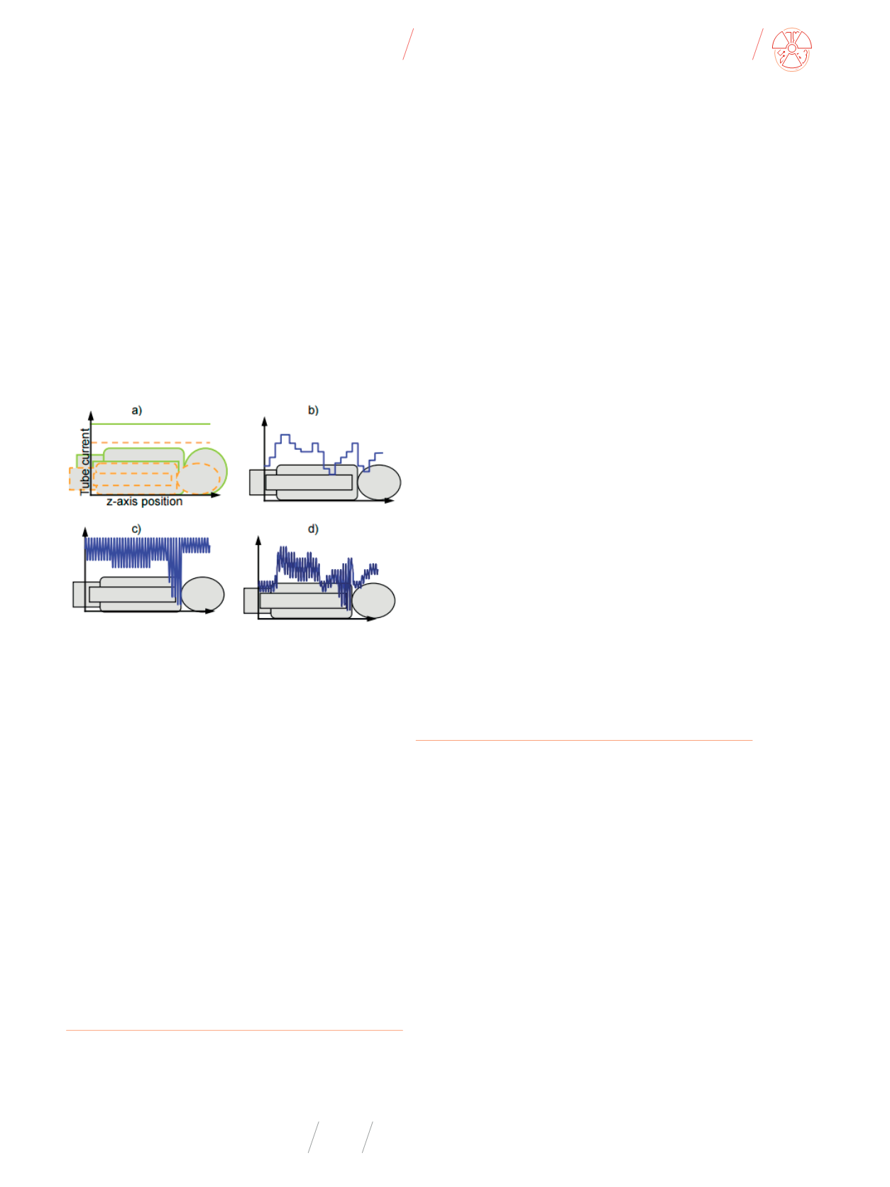
Those three levels of the AEC system can be combined (Fig.1.).
Fig. 1
(AEC) system: a) patient size, b) z-axis (AEC), c) rotational/diagonal (AEC), d)
combined (AEC)
Source: [1].
The introduction of CT AEC systems improved the consistency
of image quality. Although it does not answer the question of what
level of image quality is required for the diagnostic or radiotherapy
purposes. The consistency of image quantity is also assigned to im-
age quantity. It is not answer what consistency of image quantity is
required for the diagnostic and radiotherapy purposes.
AEC systems should also bring optimization between image
quality and dose provided to the patient (exposure optimiza-
tion), reduce tube loading, protect the CT system for extended
scan runs, reduce photon starvation artefacts. That last one re-
sult from inaccurate attenuation measurements at some scan
angles, causes by relatively small number of radiation transmit-
ted through the patient and reaching the detectors. Increasing
mA for the most attenuating scans angles can increase the accu-
racy of these attenuation measurements.
Verification of the (AEC) System
The AEC system should be controlled by specifying image qual-
ity – SD (Standard Deviation, Noise), SNR, CNR, contrast, unifor-
mity, spatial resolution and image quantity - HU, SD.
The standard deviation of pixel values determines a noise in
the image. The scanner aims to set the tube current is achieving
the requested standard deviation in the image by image basis.
Using an SD based system, the AEC is controlled by setting im-
age quality, rather than using mA modulation, which is a radia-
tion exposure related measure. Philips CT scanners use the SD
based AEC system. SD values in the image is not intuitive for that
system and user should set protocols in line with SD appropri-
ate for the clinical task. There is important to understand that
image noise in inversely proportional to the square of the tube
current, so halving the SD results in an increase in the mA (ef-
fectively patient dose), by a factor of 4. With SD based systems,
the (AEC) response to different patient sizes is pre-defined, be-
cause the aim is always to keep the image noise constant.
Some CT scanners systems use a reference mAs AEC control.
Setting an mA (or mAs) is used for a scanner protocol basing on
the reference mA value. That value is used on an average sized
patient. The AEC system assesses the patient size cross-section
using a scannogram, and adjusts the tube current relative to the
reference value.
There is not straightforward relationship between AEC sys-
tems basing on the reference mA value and reference SD.
The third method is controlling AEC systems basing on a “ref-
erence image” (reference images for different reference phan-
tom sizes – Philips Brillance). That image, scanned and judged
previously, is characterised by appropriate image quality for
a particular clinical purpose. The scanner sets the mA to match
the noise in the reference image. The main advantage of that
system is required image quality is expressed using existing clin-
ical protocols, rather than an abstract value of SD. It can result
better image quality but requires high experienced staff to pro-
vide appropriate image quality and an assessment of it.
The Philips CT Scanner AEC System
The Philips DoseRight system is composed of three indepen-
dent parts; Automatic Current Selector (ACS) Z-DOM (Longitu-
dinal Modulation), D-DOM (Angular Modulation). The ACS auto-
matically suggests the maximum mAs for each patient in order
to achieve a constant image noise level (between patients, not
throughout the scan). Z-DOM adjusts the mAs along the lon-
gitudinal direction, based upon the Surview image. D-DOM is
a rotational modulator varies mAs due to asymmetry (lower sig-
nals (e.g. lateral) contribute high noise, whilst high signals (A-P)
make minor contributions to total noise). Modulation is carried
out online during the scan using the data from the previous ro-
tation to determine what to do on the next.
DoseRight ACS is controlled by use of a reference image,
which is assigned by the user to be used for individual scan pro-
tocols. It uses an Surview (A-P and LAT) to assess the patient
attenuation in order to set the mA for all z-axis positions and
angles of a projection.


